Which components on a PCB should not be coated with conformal coating?
When dealing with conformal coating, many hardware engineers' first reaction is: "Wouldn't it suffice to just spray the entire PCB?"
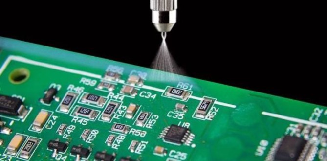
Actually, that’s not quite the case! While conformal coating does indeed enhance a PCB's resistance to moisture, salt spray, dust, and corrosive environments, it is essentially an insulating protective film. The problem lies precisely here: some components require this film, while others are adversely affected by it. This is particularly true for the components listed below; if they are coated without being masked first, the board—despite having been treated—can easily end up causing product failures. Let’s take a closer look at this issue.
I.Connectors
Connectors are typically components that must be carefully shielded during the conformal coating process; the reason is simple: reliable electrical contact is essential. For instance, a connector contact might initially have a resistance of only a few tens of milliohms; if conformal coating seeps into the contact area, it effectively creates an insulating film.
Even more problematic is the fact that while the initial mating cycle might scrape away the coating film, this does not guarantee long-term reliability. Over time, exposure to vibration and temperature/humidity cycling can lead to issues such as oxidation, contamination, or unstable contact. Therefore, in practical design, connector pins, sockets, contact areas, and mating surfaces usually require masking. This is especially critical for applications involving long-term vibration—such as automotive electronics and industrial control equipment—where the mere ability to conduct electricity should never be mistaken for true reliability.
II. Relays and Switches
Special care must be taken with contacts and moving mechanisms; relays are critical components that must be shielded from conformal coating. Relays contain internal mechanical structures such as contacts, armatures, and springs. If the coating penetrates the moving mechanisms, it may alter their operational characteristics. Of particular concern are the contacts—since relays rely on mechanical contacts for switching, any contamination of the contact surfaces can affect contact resistance, arcing characteristics, and overall reliability.
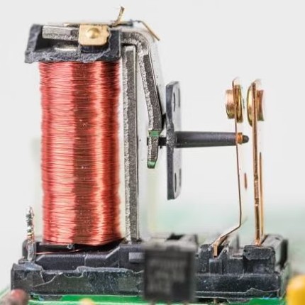
Therefore, a recommended principle is that while conformal coating can protect the PCB area surrounding a relay, care must be taken to prevent the coating from entering the relay's internal mechanisms—specifically areas involving movement or electrical contact. For high-voltage relays, additional factors such as creepage distance, clearance, and the dielectric reliability of the coating film itself must also be considered.
III. Push-buttons and Potentiometers
IV. Do not rush to apply the coating to any components that involve mechanical movement; this applies to devices such as mechanical push-buttons, potentiometers, and DIP switches. For instance, potentiometers contain internal sliding contacts; if the conformal coating seeps inside, it effectively creates a thin layer of insulating contamination over these contacts.

IV. Heatsinks and Power Components:
Power components such as MOSFETs, DC-DC converters, and LDOs are often surrounded by large copper areas intended for heat dissipation. Since conformal coating typically has much lower thermal conductivity than copper or metal, one cannot simply assume that applying a layer of coating has no impact on heat dissipation. Consider a simple thermal resistance scenario: if a power component has a power loss of P = 2W and the equivalent thermal resistance from PCB to ambient is θJA = 30°C/W, the temperature rise is approximately:
ΔT = P × θJA = 2 × 30 = 60°C
If factors such as the conformal coating, structural components, or airflow conditions cause the actual thermal resistance to increase to 40°C/W:
ΔT = 2 × 40 = 80°C
With the same 2W power loss, the component's junction temperature rises by 20°C. Therefore, for components like high-power MOSFETs, power inductors, rectifier diodes, and DC-DC chips, the critical concern is whether the overall thermal path has been compromised after coating. Special care should be taken with thermal pads, thermal vias, and exposed heat-dissipating surfaces; avoid indiscriminately covering everything just to ensure complete coating coverage.V. Optical Components
Conformal coating can directly alter the performance of components such as LEDs, photoelectric sensors, infrared receivers, cameras, and photosensitive devices; therefore, special attention is required. This is because the coating can modify the light transmittance, reflectance, or even the surface characteristics of optical windows. For instance, if a photoelectric sensor is calibrated for a specific optical window, the addition of a coating layer alters the optical path; this can ultimately result in inconsistent sensor outputs across the same batch of products.
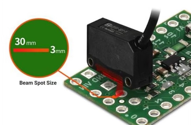
Therefore, for any component involving an optical path, it is best to follow the manufacturer's specific coating requirements rather than simply assuming that spraying over them is harmless.
A common mistake regarding conformal coating is the assumption that "more coverage is better." In reality, a more rational approach is to coat only where necessary and leave other areas exposed. Coating zones should be clearly defined during the PCB design phase by categorizing the board into three types:
① Mandatory coating zones
Examples include exposed copper traces, solder joints, standard resistors and capacitors, and areas susceptible to moisture or corrosion.② No-coat zones
Examples include connector contacts, buttons, moving parts of potentiometers, test points, and optical windows.③ Zones determined by component specifications
Components such as power devices, relays, transformers, sensors, and crystal oscillators require specific assessments rather than a "one-size-fits-all" approach.Do not rely solely on the conformal coating manufacturer's documentation; you must also consult the specific component manufacturer's coating requirements. Even among connectors, some allow coating while others explicitly prohibit it; similarly, while some MOSFETs can be fully coated, others feature heat-dissipation structures that require special handling. Truly effective conformal coating design is not about how thick the layer is, but rather about clearly defining—in advance—which areas should be coated, which should not, and the reasons behind those decisions.