DMI and CMI—Those rivals in the world EMC—what exactly are they?
DMI and CMI—Those "rivals" in the world EMC—what exactly are they?
Electromagnetic Compatibility (EMC) is an unavoidable hurdle in the development of electronic equipment. Among the various EMC issues, the two most critical and frequently encountered sources of interference are differential-mode interference and common-mode interference.
If you have handled customer feedback, you are likely familiar with this scenario: a device operates perfectly in the R&D lab, but once deployed in the field, it experiences communication errors or signal drift—and may even interfere with nearby equipment. In most cases, troubleshooting eventually traces the problem back to one of these two types of interference.
To understand the difference simply: differential-mode interference occurs between signal lines or power lines and can be viewed as internal circuit noise; common-mode interference occurs between the lines and the ground (or chassis), making it more prone to radiating outward via cables and affecting a wider area. They originate from different sources, propagate along different paths, and require different suppression techniques.
I. First, let's clarify: where exactly do they clash?
Imagine two wires on your wall: the live wire (L) and the neutral wire (N). Now, imagine the ground wire (or the chassis or PCB ground plane) as a third party.
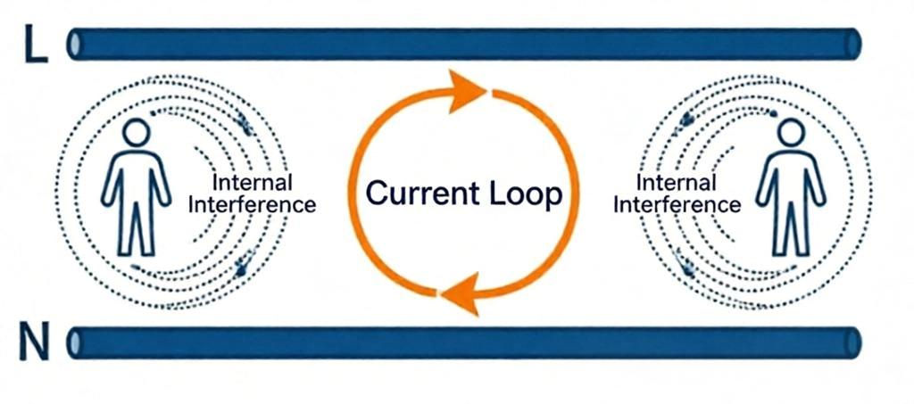
Differential-mode interference is an issue that arises specifically between the live and neutral lines. An unwanted voltage appears between them, causing current to flow out along the live line and return via the neutral line, thereby forming a closed loop. This is akin to two colleagues arguing in an office: the sound circulates within the room, so it does not seem overly loud to outsiders. Differential-mode energy is primarily concentrated in the range of a few kilohertz to 1 megahertz, with the fundamental noise of switching power supplies often clustering between 100 kHz and 500 kHz. While its higher-order harmonics can extend into the megahertz range, traces of differential-mode interference may also appear in the 3–10 MHz band if filtering is inadequate; however, since its amplitude is usually far lower than that of common-mode interference, it is rarely the primary concern.
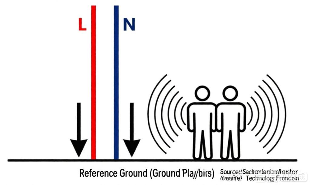
Common-mode interference occurs when the live and neutral wires "team up" to create issues relative to the reference ground. Identical interference voltages appear on both wires simultaneously; currents surge toward the ground together and then loop back via the ground wire. Imagine two neighbors standing at your doorstep shouting at you in unison—the sound spreads outward, and the entire street can hear it. This type of interference features high frequencies (above 1 MHz) and large amplitudes, and it is particularly prone to "radiation"—it is responsible for 99% of the noise your equipment broadcasts externally.
Remember this rule: differential mode is "line-to-line," while common mode is "line-to-ground (or reference plane)." Crucially, do not think of "ground" solely as the earth itself; ground planes on a PCB and equipment chassis also count.
II. How potent are they? — Let the data speak
Qualitative descriptions aren't enough; we need to know just how "severe" the interference is.Typical amplitude for differential mode: Harmonic voltages in the power grid typically reach 5% to 20% of the fundamental voltage. For instance, with a 220V fundamental voltage, harmonics might range from a dozen to over forty volts. When the switching transistor in a switched-mode power supply (SMPS) toggles, it generates differential-mode noise concentrated in the 100 kHz to 500 kHz range; if filtering is inadequate, this noise can leak directly into downstream circuits.
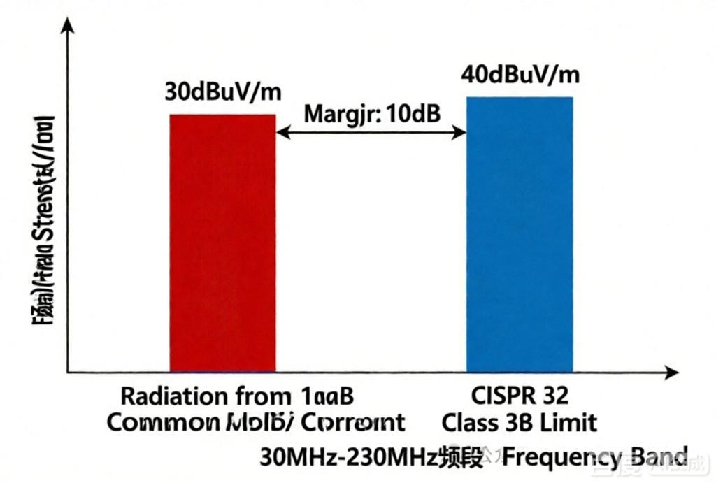
Typical radiation levels for common-mode noise: With a 1-meter-long cable, even a common-mode current of just 1 mA can generate a field strength of approximately 30 dBμV/m when measured at a distance of 3 meters in the 30 MHz range. Meanwhile, the CISPR 32 Class B limit (for household equipment) in the 30–230 MHz band is only 40 dBμV/m—meaning a 1 mA common-mode current consumes the majority of the available margin. Limits for industrial environments (Class A) are about 10 dB more lenient, yet even they cannot tolerate more than a few milliamperes. Of course, these are estimates based on typical conditions—assuming the cable length is comparable to the common-mode wavelength (approx. 1 meter at 30 MHz) and that grounding and reference conditions are ideal. Actual values may fluctuate due to factors like the chassis, grounding, and nearby metal objects, but the magnitude generally falls within this range. Ground potential difference: The grounds of different devices are often not at the same potential. In factory settings, it is very common to find a difference of several to tens of volts between the ground lines of two pieces of equipment. This voltage directly drives common-mode current to surge through signal cables; this is precisely why you might feel a tingling sensation when touching the equipment chassis.
III. Where do they come from? — Blame it on "parasitic" effects
The sources of differential-mode interference are relatively straightforward: a "dirty" power grid or "contamination" from adjacent wires via parasitic capacitance or mutual inductance. Take a transformer, for example: the distributed capacitance between the primary and secondary windings might only be 10–100 pF, yet at high frequencies, this tiny capacitance can couple spike noise from the primary side to the secondary side, manifesting as differential-mode voltage. Common-mode interference, however, arises in much trickier ways: atmospheric lightning, walkie-talkies, and the starting or stopping of large motors can all induce voltages in the same direction across cable conductors simultaneously. Then there is the ground potential difference between devices, which directly "forces" common-mode current to flow. Perhaps most insidious of all is when high-frequency square waves within the circuit leak onto the chassis via distributed capacitance and then escape outward along the cables.IV. The trickiest part—they can "transform"
Do you think differential-mode noise stays differential-mode and common-mode stays common-mode? Think again! They can convert into one another—a major pitfall in EMC design.For instance, if you route a differential pair and the length mismatch exceeds one-tenth of the signal wavelength (ΔL > λ/10), the signals on the two lines arrive at different times, causing common-mode components to emerge. Alternatively, if the return path impedance for a single-ended signal is asymmetrical—with an impedance difference exceeding 10Ω between the two sides—differential-mode signals can convert into common-mode signals. Conversely, when common-mode current flows through an unbalanced circuit (e.g., where two branches have unequal impedances), the resulting voltage drops differ; this potential difference transforms into a differential-mode voltage that superimposes directly onto your useful signal. You might go to great lengths to filter the signal, only to have all your hard work undone by this mode conversion.
V. How to Deal with Them? — A Two-Pronged Approach
Since they behave differently, the countermeasures must also differ. Don't expect a single common-mode choke to solve every problem.
Dealing with Differential-Mode Noise: Blocking and Diverting
Blocking the loop: Route signal lines close to their return paths on the PCB; the smaller the loop area, the weaker the radiation.X-capacitors (connected across L and N): Typical values range from 0.1μF to 10μF; these provide a bypass for differential-mode noise, shorting it out locally so it doesn't propagate further downstream.
Differential-mode inductors: Placed in series on the line to increase impedance for high-frequency differential-mode noise.
Dealing with Common-Mode Noise: Tough Problems Require Tough Measures
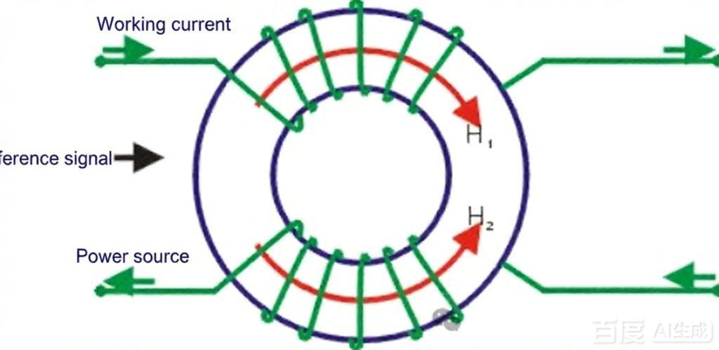
Tackling Common-Mode Noise: Tough Problems Call for Tough Measures
Common-mode chokes (common-mode inductors): Two coils are wound in opposite directions on the same magnetic core. When common-mode current flows, the magnetic fields align, causing inductance to surge—effectively "choking" the noise. Conversely, when normal differential-mode current flows, the magnetic fields cancel each other out, resulting in near-zero inductance and allowing the signal to pass unimpeded. Core material selection is critical: Manganese-Zinc (MnZn) ferrite suits low frequencies (tens of kHz to a few MHz), while Nickel-Zinc (NiZn) ferrite suits high frequencies (tens of MHz and above). Excessive turns can lead to core saturation, rendering the component ineffective.
Y-capacitors (Line/Neutral to Earth): These provide a path for common-mode noise to shunt to ground. Typical values are ≤4.7nF, but the specific upper limit is dictated by safety standards (IEC/UL/GB) and the device's leakage current rating. Requirements vary by region and product category; for instance, Type CF medical equipment is extremely sensitive to leakage current, often limiting Y-capacitor values to the tens or hundreds of pF range. Do not aim for excessive capacitance; exceeding leakage current limits poses a shock hazard—safety standards are not to be taken lightly.
Shielding and Grounding: Shields require 360° termination; avoid "pigtails" at all costs. For low-frequency common-mode noise (e.g., power line frequency), use single-ended grounding to prevent ground loops; for high-frequency noise (MHz range and above), use dual-ended grounding to lower impedance. Crucially, the decision to use dual-ended grounding must account for potential differences between system grounding points; in complex systems, dual-ended grounding can introduce ground loops caused by potential differences, proving counterproductive. For digital signal lines and RF shielded cables, the preferred approach is 360° bonding of the shield via the connector shell, while maintaining a single-point reference for signal ground.
Differential Transmission: Protocols like RS-485 and CAN possess inherent common-mode noise immunity. However, note the termination strategy: place a single 120Ω resistor only at the two furthest nodes of the bus, rather than at every node. Also, do not overlook common-mode biasing resistors (pull-up/pull-down); without them—relying solely on termination resistors while ignoring fail-safe biasing—the bus may enter an indeterminate state during idle periods.
VI. How to distinguish the nature of the issue during debugging? — Tools and techniques
Upon receiving a Radiated Emission (RE) or Conducted Emission (CE) test report, you can use the frequency bands exceeding the limits to make an initial assessment of the problem area, quickly identify key points for troubleshooting, and avoid guesswork.
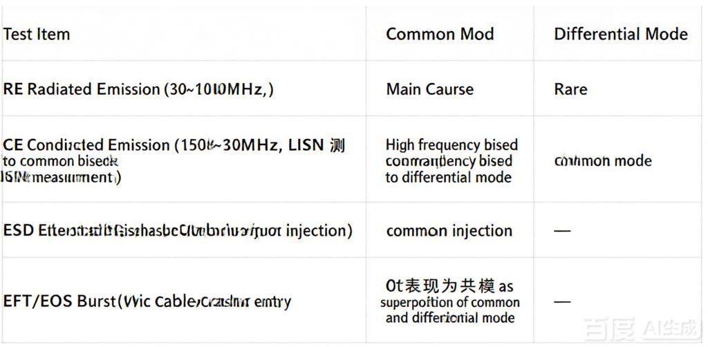
In practice, the diagnosis can be approached as follows: for low-frequency conducted emissions (<1 MHz) exceeding limits, first check if the X-capacitor capacitance is too low or if the differential-mode inductance is insufficient; for high-frequency conducted emissions (>1 MHz) or radiated emissions exceeding limits, prioritize checking the suitability of the common-mode choke selection, the proper placement of Y-capacitors, and the reliability of the shielding ground connection.
VII. A Veteran Engineer’s Hard-Learned Lessons (Avoiding Pitfalls)
Many PCB layout issues stem from a failure to distinguish between differential-mode and common-mode noise; the seeds of trouble are often sown during the PCB design phase.
Differential-Mode Suppression (PCB):
Ensure tight coupling between the signal and its return path—use microstrip or stripline structures whenever possible to ensure a continuous reference plane directly beneath the signal line.
Route power and ground lines as a pair to avoid creating large "floating loops."
Minimize the high-frequency current loop area between the switching transistor and the freewheeling diode; this is the primary source of differential-mode noise in switching power supplies.
Common-Mode Suppression (PCB):
Maintain the integrity and continuity of the ground plane; specifically, avoid splits or voids beneath interface areas, as these force common-mode currents to take circuitous paths, thereby increasing radiation.
Avoid routing signal lines across ground plane splits—crossing a split interrupts the return path, forcing common-mode current to take a long detour and effectively creating a radiating antenna.
Clearly define the connection method between Chassis GND and Signal GND in interface areas—typically via a star-point connection or a bridging capacitor; improper handling here allows common-mode interference to propagate directly out along the cables.
VIII. How to Make a Rough Assessment of Differential-Mode vs. Common-Mode Noise Using Existing Tools?
High-end equipment is not strictly necessary. A preliminary assessment can be made using a LISN (Line Impedance Stabilization Network) paired with a standard oscilloscope; this is a low-cost approach that eliminates the need for guesswork. The procedure involves using a LISN to measure the noise voltages on the Line (L) and Neutral (N) conductors separately, followed by two simple calculations:Differential-mode component ≈ |V_L − V_N| / 2
Common-mode component ≈ (V_L + V_N) / 2
Observing the waveform on an oscilloscope allows for further differentiation of noise types—such as switching spikes versus power-line frequency harmonics—providing a quick visual assessment. While this method cannot replace standard compliance testing, it is highly practical for troubleshooting and determining the direction of a fix.
IX. Hard-Learned Lessons from Veteran Engineers
Don't buy common-mode chokes haphazardly: Select the core material based on frequency—Mn-Zn (Manganese-Zinc) for low frequencies and Ni-Zn (Nickel-Zinc) for high frequencies. Look beyond the nominal inductance value; consider the actual impedance at the specific interference frequency.Bigger isn't always better for Y-capacitors: High capacitance leads to excessive leakage current, which can cause medical or portable devices to fail safety standards. Safety comes first; adhere to regulatory standards.
Twisted pairs aren't a cure-all: While they suppress differential-mode radiation and cancel common-mode noise, proper termination (120Ω) is essential. Without it, reflections can generate far more common-mode noise than anticipated.
A solid ground plane isn't always ideal: Arbitrary segmentation of the ground plane forces common-mode currents to take longer paths, potentially increasing radiation. The key is minimizing the high-frequency return path.
Don't cut corners on shielding grounds: Using a long lead wire to ground the shield renders it ineffective at high frequencies; a 360° connection is required.
Place RS-485/CAN termination resistors correctly: Install a 120Ω resistor only at the two furthest nodes of the bus. Do not place one at every node, or the bus's driving capability will be severely compromised.
X. Times Have Changed, and New Problems Have Arisen
Modern technologies have exacerbated the conflict between these two "adversaries":800V platforms for new energy vehicles: SiC power devices switch extremely fast, with dv/dt rates exceeding 50 kV/μs—and sometimes even reaching 100 kV/μs. This injects common-mode current into the ground line via parasitic capacitance, resulting in measurable common-mode noise of 800 mV in the 10 MHz frequency range. Simply adding ferrite beads is usually insufficient for such systems; effective control of common-mode radiation requires reducing dv/dt at the source (e.g., by adjusting gate resistors or employing active clamping) and combining this with multi-stage common-mode filtering, shielded cabling, and system-level equipotential bonding.
5G base stations: Common-mode coupling occurs between massive MIMO antenna arrays and power lines at GHz frequencies; traditional ferrite beads fail in this range, necessitating the use of new materials.
Low-power IoT devices: These operate at low voltages with tight power budgets and are highly sensitive to ripple; differential-mode noise levels that were previously tolerable can now cause chips to reboot. Power integrity calculations must be re-evaluated.
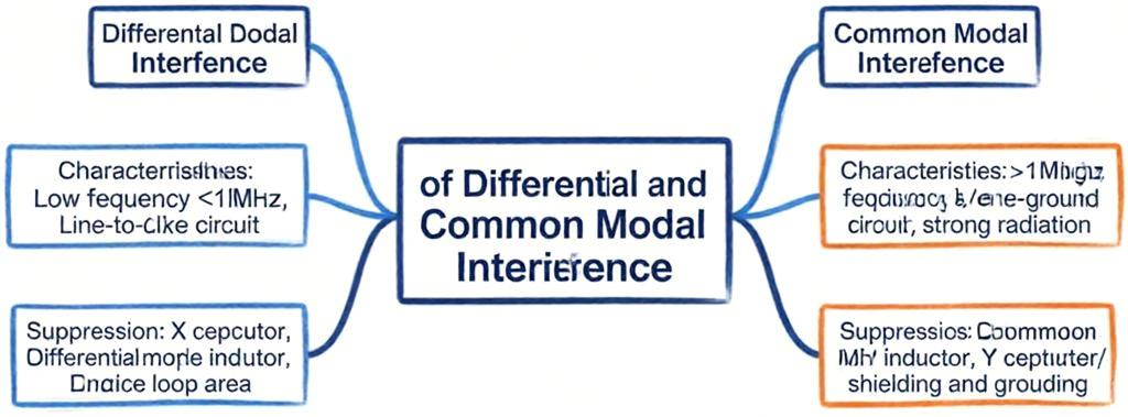
To summarize briefly: common-mode noise is primarily radiated, while differential-mode noise is primarily conducted. Of the two, common-mode noise is the primary issue; once it is suppressed—using shielding, grounding, and common-mode chokes—addressing differential-mode noise through X-capacitors and circuit optimization becomes much easier.
When dealing with EMC, many people immediately focus on differential mode because it is directly related to the signal and easy to measure. However, common mode is the true "silent killer"—it generates strong radiation, is difficult to detect, and can convert into differential mode. Therefore, the correct approach is to prioritize common-mode mitigation during design and address differential mode subsequently; during testing, examine high frequencies first (where common-mode issues are most prevalent) before checking low frequencies.
Once you fully grasp the nature and characteristics of these two types of interference, passing EMC tests becomes significantly easier. The key lies in mastering the right methods and tools to accurately pinpoint issues. EMC is not a mystical art but a science—one that relies on a solid understanding and the accumulation of experience.