When is isolation required for RS-485, and when is it not?
When working with RS-485 communication, many hardware engineers encounter a question that appears simple but is actually a potential pitfall: is isolation truly necessary for RS-485? Some argue that isolation is required for distances exceeding a few dozen meters, while others contend that it is mandatory in industrial environments. So, what is the actual deciding factor for whether RS-485 requires isolation? Is the communication distance the only criterion to consider?
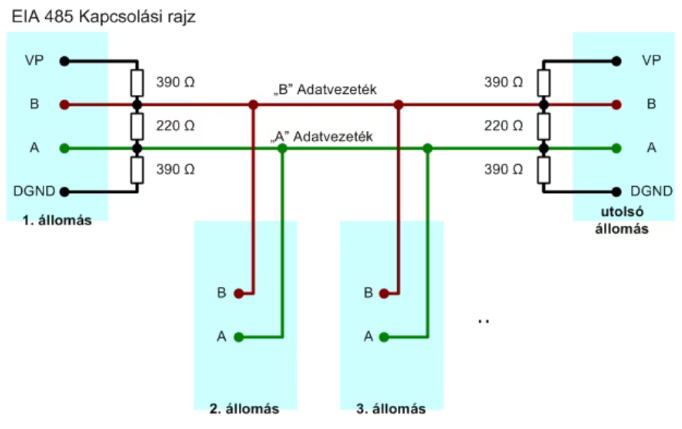
In reality, the key factor isn't the communication distance itself; rather, it’s the ground potential difference between two nodes, the presence of common-mode interference, and whether there is a requirement for high-voltage or safety isolation. Once these factors are clarified, determining whether an RS-485 system needs isolation becomes straightforward. Let’s explore this topic today.
First, we need to understand: why does an RS-485 system require a ground connection in the first place?
RS-485 utilizes differential transmission, where a differential voltage is transmitted across two lines—A and B. Theoretically, the receiving end is concerned only with:
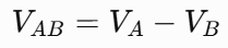
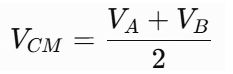
This voltage is measured relative to the ground (GND) at the receiving end. The traditional TIA/EIA-485-A standard specifies a typical common-mode operating range of -7V to +12V. In other words, even if the differential voltage between lines A and B is perfectly correct, an excessive potential difference between the grounds at either end can push an RS-485 transceiver outside its normal operating range. This is one of the fundamental reasons why RS-485 systems require isolation.
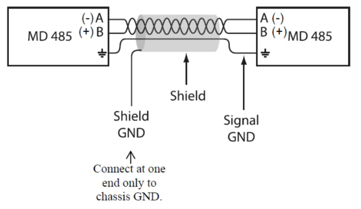
If two RS-485 nodes share a common ground, are located close to each other, exhibit no significant ground potential difference, and operate within the same electrical environment, it is generally unnecessary to force the inclusion of isolation—even if the application falls under the category of "industrial communication." For instance, in a setup such as MCU → RS-485 → sensor, where both devices are powered by the same 24V supply, their respective ground (GND) potentials will naturally be very close; in such cases, the common-mode voltage at the RS-485 transceiver typically remains well within its specified operating range.
Furthermore, some designs utilize non-isolated RS-485 transceivers with an extended common-mode range to enhance fault tolerance. For example, certain reference designs from ADI feature non-isolated solutions capable of handling a common-mode range of ±25V, which can help eliminate the need for isolation in specific application scenarios.
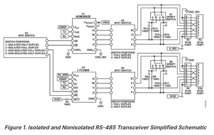
However, there is a crucial concept to keep in mind: a long communication distance does not automatically necessitate isolation. For an RS-485 link spanning 100 meters, if both ends share a reliable power system—resulting in a negligible ground potential difference—isolation may not be required. Conversely, even over a distance of just 10 meters, if the two ends are connected to entirely different power systems, a potential difference of several volts, tens of volts, or even more could exist between their respective grounds (GND); in such cases, isolation becomes absolutely essential.
So, when is isolation strongly recommended?
From a hardware perspective, there are four key scenarios to consider:
1. The two ends belong to different power supply systems.
For example, in a setup involving a PLC, an RS-485 link, and a variable-frequency drive (VFD): the PLC might be powered by an independent 24V supply, while the VFD contains high-interference circuitry—such as rectifiers, inverters, and PWM switching components. In this case, even if the RS-485 cable is only a few meters long, a significant ground potential difference can still arise between the two devices. In applications like motor drives or factory automation, the ground potential difference between a PLC and a drive can easily exceed the limits specified for the RS-485 standard; therefore, isolation is typically required.
2. Large distance between endpoints, resulting in a ground potential difference (GPD)
Suppose there is a ground potential difference (VGPD) of 10V between two devices. If the RS-485 transceiver’s own output common-mode voltage (VOC) is 1V and the noise coupled from the environment (VN) is 3V, the common-mode voltage (VCM) seen at the receiving end could reach: VCM = VGPD + VOC + VN = 10 + 1 + 3 = 14V.In this scenario, while the differential voltage (VAB) might still appear normal at around 2V, the common-mode voltage has exceeded the +12V upper limit typical for standard RS-485 interfaces. This could lead to more than just occasional communication errors; in severe cases, it may cause the transceiver to malfunction or even sustain permanent damage. Therefore, do not simply rely on an oscilloscope to check if the A-B waveform looks "clean"—you should also measure the voltages of lines A and B relative to the local ground (GND).
3. Presence of strong interference in industrial environments
Equipment such as variable-frequency drives (VFDs), servo drives, motors, high-power relays, and contactors—as well as long-run outdoor cabling—can introduce common-mode interference into RS-485 lines. When RS-485 cables are routed over long distances, they can effectively act as antennas. In this context, isolation serves a purpose beyond merely blocking DC voltage; more importantly, it breaks the direct current path between different ground potentials, thereby reducing interference caused by ground loops.
4. Applications involving personnel safety or high-voltage systems
In these cases, cost should not be the primary concern. Examples include architectures such as mains-powered systems connected to controllers via RS-485, or high-voltage battery systems interfaced with a Battery Management System (BMS) or controller. In communication interface architectures, if an RS-485 link connects systems with different voltage levels, isolation ceases to be merely a matter of communication reliability—it becomes a critical safety requirement.In such cases, one must go beyond simply selecting an isolated RS-485 transceiver chip; it is necessary to carefully evaluate factors such as isolation withstand voltage, operating voltage, creepage distance, clearance, and the required level of basic or reinforced insulation.
Finally, beware of a common pitfall: isolating the signals while failing to isolate the power supply.
This is a classic error in RS-485 system design. Suppose the MCU side is referenced to GND1 and the RS-485 bus side to GND2; if you use a digital isolator to separate the TXD and RXD lines, but the RS-485 transceiver’s VCC and GND pins are still derived from the GND1 domain, the isolation barrier is effectively bypassed by the power supply. In this scenario, the effectiveness of the "isolated" RS-485 setup must be re-evaluated. A truly robust isolation scheme typically requires both signal isolation and an independent power supply for the RS-485 side—often implemented using an isolated DC/DC converter.
Therefore, for RS-485 systems that must contend with significant ground potential differences, it is essential to implement isolation across both the signal and power supply paths.