
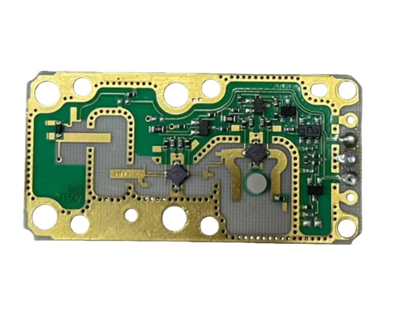
24GHz Radar PCBA
A 24GHz Radar PCBA (Printed Circuit Board Assembly) is a highly integrated circuit module specifically designed
for radar systems operating within the 24GHz frequency band;it is widely utilized in fields such as drone altitude holding,
industrial distance measurement, and intelligent transportation. Depending on specific design objectives,
its performance parameters and hardware configurations can vary significantly.
ISTRA24 24GHz Drone Altimeter Radar (Miniaturized Version)
Altitude Range: 0.2m – 50m
Update Rate: 50Hz (highly real-time)
Dimensions: 45 × 45 × 6mm (PCBA); lightweight and compact
Weight: Only 6.5g; ideal for integration into micro-aerial vehicles
Interface: UART-TTL; default communication baud rate of 115,200 bps
Operating Voltage: 4–5.5V (independent power supply recommended)
TINYRAD 24GHz Radar Evaluation Board (EV-TINYRAD24G)
A multi-functional radar development platform designed for industrial and research applications.Distance Resolution: 60cm; maximum detection range of up to 100m (RCS = 1m²)
Beamwidth: 75° (Azimuth), 15° (Elevation)
Supports MIMO technology, achieving an azimuth resolution of up to 20°
Integrates key components including the ADF5901 Transmit MMIC, ADF5904 Receive MMIC, and ADSP-BF706 DSP
Connects to a PC via USB; utilizes accompanying GUI software to visualize "Range-Doppler Maps" and "Range-Angle Maps"
Includes MATLAB and Python algorithm code to facilitate secondary development
Materials
24 GHz radar PCBAs impose stringent requirements on high-frequency performance; a critical aspect of their design is the selection of specialized
high-frequency laminates characterized by low loss and stable dielectric constants. In practical engineering applications,
Rogers RO4350B and Taconic RF-35 stand out as two mainstream,proven, and preferred material choices.
I. Rogers RO4350B: A Cost-Effective Industry Benchmark
RO4350B is a high-frequency laminate introduced by Rogers Corporation, featuring a hydrocarbon resin and ceramic filler system that delivers exceptional electrical and thermal stability:Dielectric Constant (Dk): 3.48 ± 0.05 @ 10 GHz; offers excellent frequency stability, ensuring phase consistency.
Dissipation Factor (Df): 0.0037 @ 10 GHz; significantly lower than standard FR4 (>0.02), allowing signal attenuation to be controlled within 1.5 dB/m at 24 GHz.
Coefficient of Thermal Expansion (CTE): Well-matched with copper foil in the X and Y directions, thereby reducing the risk of warping caused by thermal stress.
Process Compatibility: Compatible with standard FR4 processing workflows; suitable for hybrid multilayer structures (e.g., high-frequency outer layers combined
with FR4 inner layers),which lowers costs while maintaining performance. Applications: Suitable for radar systems operating in the 24 GHz to 30 GHz frequency bands,
and particularly well-suited for cost-sensitive applications with high performance demands,such as automotive Short-Range Radar (SRR) and industrial sensors.
II. Taconic RF-35: A Reliable Choice for Lightweight High-Frequency Applications
Taconic RF-35 is a PTFE-based high-frequency laminate renowned for its ultra-low loss and lightweight characteristics:Dielectric Constant (Dk): ≈ 3.5; similar to RO4350B, facilitating easy design migration.
Dissipation Factor (Df): < 0.004; offers excellent signal integrity at high frequencies.
Lighter Weight: Compared to RO4350B, it is better suited for weight-sensitive applications (e.g., drones and portable devices).
Processing Considerations: PTFE material requires specialized processing techniques (such as plasma drilling) to prevent delamination or insufficient adhesion.
Applications: Ideal for scenarios requiring both lightweight design and high-frequency performance, such as altitude-holding radar
for drones and obstacle avoidance systems for mobile robots.
III. Why Is Standard FR4 Not Recommended?
Despite its low cost, FR4 suffers from significant drawbacks:Its dielectric constant is unstable (varying significantly with frequency), leading to increased phase errors.
It exhibits a high loss tangent; attenuation can reach up to 10 dB per meter at 77 GHz, and its performance at 24 GHz is also markedly inferior to that of high-frequency laminates.
It is sensitive to temperature and humidity, making it prone to performance drift during long-term operation.
Consequently, in frequency bands of 24 GHz and above, the use of standard FR4 for RF routing layers should be strictly avoided;
it may be utilized only in hybrid stack-up designs for digital or power layers.
Production Precautions
During the production of 24GHz radar PCBAs, strict control over high-frequency circuit manufacturing processes and material consistency is essential;
even the slightest deviation can lead to a significant degradation in signal performance.
The following are key production considerations:
I. Material and Lamination Control
Incoming Material Inspection:Ensure the use of specified high-frequency materials (e.g., Rogers RO4350B or Taconic RF-35) and
verify the actual measured values of the dielectric constant (Dk) and dissipation factor (Df) to prevent batch-to-batch variations.Hybrid Lamination Alignment:If a stacked design incorporating high-frequency layers and FR4 inner layers is adopted,
ensure that the coefficients of thermal expansion (CTE) of the different materials are matched to prevent warping during the lamination process.Board Thickness Tolerance Control:The total board thickness is recommended to be controlled within ±0.1mm,
as this directly impacts the impedance accuracy of the microstrip lines.
II. Impedance and Routing Processes
First Article Impedance Testing:For every production batch, the first manufactured board must undergo Time Domain Reflectometry (TDR) testing
on critical RF traces to verify an impedance of 50Ω ±5%.Line Width/Spacing Precision:For microstrip lines—typically ~0.6mm in width (using RO4350B with 1oz copper)
—the etching tolerance should be maintained at ≤±10% to prevent impedance mismatch.Corner Treatment:Right-angle routing is strictly prohibited; instead,
uniformly employ 45° chamfers or curved bends to minimize high-frequency signal reflections.
III. Via and Grounding Processes
Back-Drilling:For long vias in multi-layer boards, back-drilling must be performed to eliminate parasitic resonances caused by via stubs,
which have a particularly significant impact in the 24GHz frequency band.Ground Via Array Density:Place a row of ground vias on both sides of
the RF traces at intervals of λ/10 (approximately 1.25mm) to form a "via wall," thereby suppressing crosstalk.PTH Copper Thickness:A minimum copper thickness of ≥20μm is recommended for Plated Through Holes (PTH)
to ensure low impedance in the high-frequency return current paths.
IV. Antenna and Surface Finish
Solder Mask Opening:The antenna's radiating area must feature a completely exposed copper surface; covering it with solder mask ink is strictly prohibited,
as doing so would result in a gain reduction of 3–5 dB.Preferred Surface Finish:The use of Electroless Nickel Immersion Gold (ENIG) or
Organic Solderability Preservative (OSP) is recommended;avoid Hot Air Solder Leveling (HASL),
as the resulting uneven surface can degrade high-frequency performanceSMD Antenna Dimensional Accuracy:
The dimensions of the antenna element must be controlled within a tolerance of ±0.05 mm,
and the feed point offset must be ≤0.1 mm to prevent beam deflection.
V. Shielding and Thermal Management Structures
Shielding Can Placement:A clearance height of >3 mm must be reserved for the shielding can to prevent contact with internal components,
which could trigger self-resonance.Thermal Via Array:A Thermal Via Array (0.3 mm diameter, 0.8 mm pitch) should be placed beneath
power devices and filled with thermally conductive resin to enhance heat dissipation.Solder Mask Opening for Thermal Enhancement:
Solder mask openings should be added to large copper foil areas to allow for solder coating, thereby enhancing thermal dissipation capabilities.
VI. Testing and Verification
S-Parameter Testing:Use a Vector Network Analyzer (VNA) to measure S11 (Return Loss);
a value of <-15 dB at 24 GHz is required to ensure proper impedance matching.
Near-Field Scanning:Employ a near-field probe to detect electromagnetic leakage hotspots,
thereby identifying defects in routing or shielding.Functional Programming and Calibration:An automated calibration routine must be integrated into
the production line to compensate for phase deviations caused by component tolerances.
As the core platform for high-frequency microwave systems, the 24GHz radar PCBA directly determines the radar's range resolution,
detection accuracy, and environmental adaptability.
These boards are subject to rigorous requirements regarding material selection, manufacturing processes,
and reliability design; any oversight at any stage could result in signal distortion or functional failure.


