
Understanding the DDR JEDEC Standard Core
Many people associate JEDEC with the "bible of DDR." This is only half true. While JEDEC does define many fundamental rules for DDR, it doesn't solve all the problems related to controllers, PHYs, board levels, packaging, BIOS, training, and mass production consistency. Truly understanding JEDEC isn't about memorizing standard numbers, but about understanding what it defines as "must be standardized" and what issues it leaves to chip manufacturers, module manufacturers, motherboard manufacturers, and system engineers.Those working in DDR often say, "It depends on JEDEC." But if you delve deeper—what exactly does JEDEC look at? Does it specify timings or voltages? Does it dictate board routing? Does it tell you how the controller schedules? Does it hardcode the training algorithm? Many people haven't truly thought this through. Therefore, in this article, we do not intend to write a bunch of dry clauses about JEDEC. Instead, we want to explain it thoroughly from an engineering perspective: what exactly does the JEDEC standard cover, what does it not cover, why does it only cover these things, and what is its relationship with datasheets, controllers, PHYs, DIMMs, SIPI simulations, and board-level design.
JEDEC's position in the DDR world: It's like "traffic regulations"—first, unify the language and rules, then let each company make products within those rules.
I. What exactly is JEDEC? Why is it indispensable for DDR?
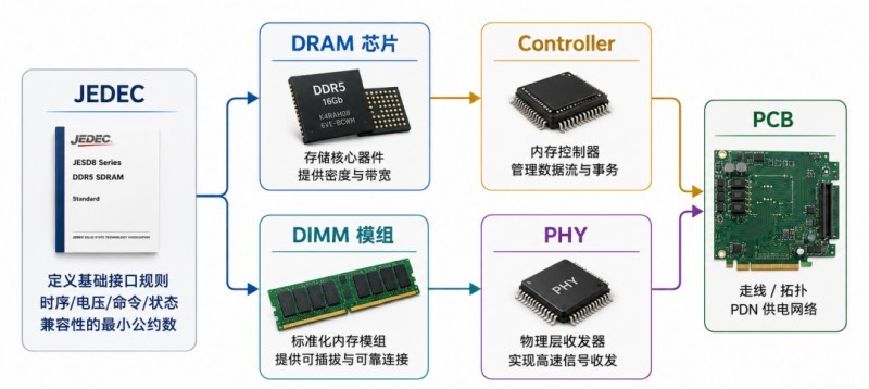
JEDEC was originally an industry standards organization, and its value is not mysterious: to establish a common language and rules for the semiconductor and memory industries. Without these rules, if each DRAM manufacturer followed its own interface, voltage, timing, and command system, controller manufacturers, CPU manufacturers, motherboard manufacturers, and module manufacturers would suffer greatly: today they would adapt to manufacturer A's chips, tomorrow they would switch to manufacturer B and find that everything was incompatible.
Therefore, the role of JEDEC is essentially to allow the industry chain to agree on a "common bottom line": what this generation of DDR is called, how the pins are defined, how the I/O electrical works, what commands are available, how initialization is performed, how timing parameters are understood, and where the compatibility boundaries are. In this way, different manufacturers can make products around the same set of rules.
To use a very practical analogy: JEDEC is a bit like traffic regulations on a highway. It doesn't build the car for you, teach you how to achieve the fastest lap time, or guarantee you won't get stuck in traffic; but it must first define whether you drive on the right or left, stop at red lights or go at green lights, what the speed limit is, and how the lanes are marked. Without these, the entire system cannot function properly.
JEDEC's core value isn't "making products," but rather "enabling products from different companies to collaborate under the same set of fundamental rules."
For DDR, commonly encountered standards typically include: JESD79 series: SDRAM device standards such as DDR3, DDR4, and DDR5.
JESD209 series: LPDDR standard.
Module-related standards: For example, certain mechanical, electrical, and SPD-related conventions of DIMM modules are reflected in other standards. You'll find that these standards are primarily "device-level, interface-level." Their goal isn't to teach you how to design an entire system, but rather to unify the interface layer that the entire industry chain relies on.
II. What exactly does JEDEC define?
This is the most crucial question in the entire document. Many people overestimate or underestimate JEDEC. In reality, JEDEC primarily defines the parts that, if not standardized, will cause cross-vendor compatibility issues.
1. It defines the interface and pin semantics. For example, which are DQ, which are DQS, which are CA, which are CK, and which are CKE, CS, ODT, RESET, ALERT, PAR, and DBI? The standard clearly defines the function, direction, and basic semantics of each signal. Otherwise, the controller wouldn't know how to communicate with the DRAM.
2. It defines the basic electrical boundaries, including operating voltage, input/output thresholds, reference voltage concepts, signal swing, AC/DC conditions, power-on sequence, and power supply relationships. Simply put, it defines the voltage range in which this interface should operate, what voltage level is considered 0, what voltage level is considered 1, and under what conditions it is valid.
3. It defines commands and state machines, such as ACT, READ, WRITE, PRECHARGE, REFRESH, and MRS, specifying their meanings, timing relationships, and enabled/disabled state transitions. Without these, the controller and DRAM wouldn't even have a proper "access flow." JEDEC tells you when a command can be issued and how long you must wait before another command can be issued.
4. It defines key timing parameters, such as the familiar CL, tRCD, tRP, tRAS, tRC, tFAW, tCCD, tWR, tRFC, and tREFI. Note that a key contribution of JEDEC is not just providing numerical values, but defining "what this parameter actually means." For example, tRCD is the minimum interval from ACT to READ/WRITE, tRP is the recovery time required for PRECHARGE, and so on.
5. The standard defines initialization, mode registers, and basic characteristics. It specifies the fields in the mode register, how certain functions are enabled or disabled, the general framework of the initialization process, and how certain low-power modes, verification, and training support mechanisms are accessed.
6. The standard sets fundamental compatibility goals. Compatibility doesn't mean "all products are exactly the same," but rather "under a set of standards, controllers from vendor A and DRAM from vendor B should have interoperability." JEDEC doesn't guarantee 100% mass production success, but it provides a common starting point.
| JEDEC's Content | Unified Specification | Consequences Without Specification |
| Pin/Signal Definition | "Who is Who" | The controller and DRAM cannot communicate and connect properly |
| Command Semantics and State Transition | Access Protocol Language | One party sends a command while the other party misinterprets it |
| Key Timing Parameter Definition | Latency and Boundary Specifications | System stability and compatibility cannot be guaranteed |
| Operating Voltage / Threshold / AC/DC Characteristics | Electrical Foundation | Products from different manufacturers are difficult to interoperate |
| Mode Register / Initialization | Device Configurable Entry | Configuration methods of different products cannot work in coordination |
| Refresh / Low Power / Reliability | Basic Behavior Model | System software and controllers are difficult to adapt to the hardware |
By now you should be able to see that JEDEC's focus is not on "explaining all the design details," but on defining the interface layer rules that must be unified across different manufacturers.
III. What Does JEDEC Not Specify? Why Specifically, Why Not Specify These Things?
This question is more important than "what is specified." Many engineering disputes stem precisely from the misconception that JEDEC should specify everything.
1. It won't specify how your controller's internal design should be. How the controller schedules requests, implements bank/row policies, handles QoS, performs address mapping, balances bandwidth and latency, and handles refresh and insertion are generally not within the scope of JEDEC's direct specifications. This is because it falls under the controller manufacturer's implementation capabilities and product differentiation space.
2. It won't specify the specific circuit implementation of the PHY. For example, how to design DLLs/PLLs, implement sampling circuits, generate Vrefs, implement DQS gating, optimize read/write leveling algorithms, and elaborate on the internal implementation architecture of DFE/ODT/drive strength are not things that JEDEC hardcodes. The standard may provide behavioral or interface requirements, but it won't provide the circuit diagrams.
3. JEDEC doesn't dictate PCB routing. Topology selection, fly-by or point-to-point routing, equal-length routing, via optimization, layer stacking, reference plane cutting, return path assurance, and decoupling layout are all board-level design and SIPI (System-in-Package) domains. JEDEC can only tell you the electrical boundaries of the interface; whether you can implement that interface well on the board is a matter of your engineering capabilities.
4. JEDEC won't solve packaging and system coupling issues for you. In real systems, packaging, substrate, BGA breakout, PCB, connectors, DIMM slots, and power networks all affect signal integrity and power integrity. JEDEC won't say, "A certain generation of DDR must use a certain number of layers, must use this PDN, must place capacitors this way." This is because these are highly dependent on the specific platform, cost targets, and product form factor.
5. JEDEC doesn't guarantee "zero-debugging interoperability" between any two products. This is a huge misconception. Many people think, "If it conforms to JEDEC, it's guaranteed to be compatible without question." In reality, JEDEC provides common rules, but systems may still require adjustments due to differences in controller implementation, DRAM characteristics, BIOS parameters, training strategies, board-level SI/PI margins, temperature and voltage cornering, etc. JEDEC aims to ensure "communication," not "automatic high scores."
A crucial fact to remember:
The JEDEC standard is not a production guarantee. It defines the basic boundaries of compatibility, but it does not assume responsibility for implementation quality, board design, package constraints, training optimization, and mass production consistency.
IV. Why can't JEDEC regulate everything?
Because if JEDEC regulated everything, the industry would lose its vitality. The responsibility of standards organizations is usually to define a "consensus at the interface layer that must be unified," not to eliminate implementation differences between all manufacturers. The reason controller manufacturers, CPU manufacturers, DRAM manufacturers, and module manufacturers can still compete is because there is still a lot of room for optimization and differentiation within the same standard. In other words, JEDEC only regulates those things that require unification to work together; while those things that maintain compatibility and allow manufacturers to continue to innovate are often left to the industry to do. The boundaries of standards are very important: too little regulation leads to incompatibility; too much regulation stifles innovation.
V. What is the relationship between JEDEC, Datasheet, Controller, PHY, and DIMM?
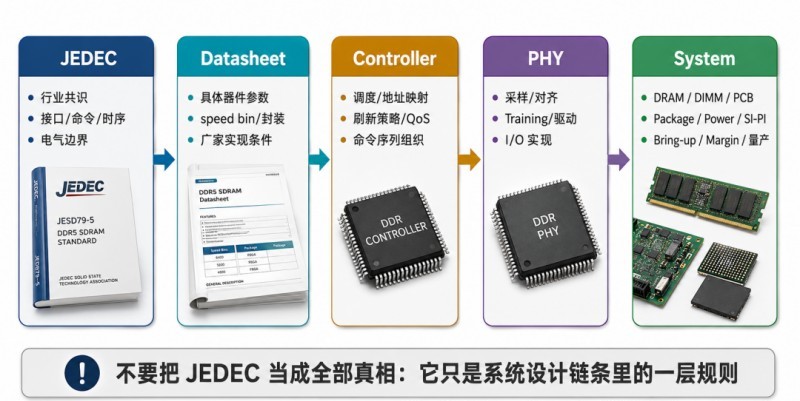
This is the part that many newcomers easily confuse. You can understand them as unfolding layer by layer from "commonality" to "individuality."
1. JEDEC: Industry-wide common rules. It defines the general framework that everyone must follow, emphasizing universality and compatibility.
2. Datasheet: Specific device implementation specifications. Even for DDR4/DDR5 chips that conform to JEDEC, different manufacturers, capacities, speed bins, and packages will still have their own actual parameters and conditions. JEDEC is like a constitution, and the datasheet is like a specific product manual.
3. Controller: The system scheduling brain. The controller interacts with DRAM according to the JEDEC language, but how it issues commands, how it queues, and how it improves bandwidth utilization belong to the implementation layer.
4. PHY: The interface implementer. The PHY translates the controller's logical intent into actual high-speed electrical signals and is responsible for training, sampling, alignment, read/write timing, and other issues. It conforms to JEDEC interface requirements, but the implementation methods can vary greatly.
5. DIMM/PCB/Package: Turning standards into physical paper rules into mass-produced products requires the implementation of modules, packages, PCBs, and power networks. This is the part outside of JEDEC that is most prone to problems and best reflects engineering capabilities.
VI. A very real problem: Even with JEDEC compliance, why do projects still fail?
This problem is a stark reflection of many DDR projects: the chosen SoC supports JEDEC DDR5, the selected chips are JEDEC compliant, and the module is a mainstream solution, yet system setup still presents a host of problems. Why?
Because a real system isn't a "standard document puzzle," but rather an "implementation quality puzzle." The following issues are not automatically resolved by JEDEC:
• Are the board-level topology and length control reasonable?
• Is the SI/PI coupling between the package and the board level underestimated?
• Are the training parameters properly tuned?
• Are Vref, ODT, and drive strength within the appropriate window?
• Is the PDN sufficiently clean, and are VDD/VDDQ/VPP noise controllable?
• Are there sufficient margins in temperature, voltage, and process corners?
• Have the differences between different manufacturers' NAND flash memory been masked by the BIOS or firmware?
• Does address mapping and Rank/Bank organization affect efficiency and stability?
All of this illustrates one point: JEDEC is responsible for defining the "language," but not for how well you "speak." Compatibility is just the starting point, not the end. The correct understanding from an engineering perspective: JEDEC is the "foundation for cross-vendor interoperability," not the "magic weapon for system startup." The key to success in mass production is JEDEC + Datasheet + Controller/PHY implementation + packaging + PCB + PDN + Training + Verification.
VII. Six Common JEDEC Misconceptions in Engineering
Misconception 1: JEDEC specifications guarantee perfect compatibility. False. JEDEC only defines the language foundation for compatibility; it doesn't mean all implementations are problem-free. System-level implementation and margins also matter.
Misconception 2: Things not written in JEDEC are unimportant. False. Board-level SI/PI, PDN, layout, training strategies, and packaged return paths can all determine a project's fate, but they don't fall under the category of "industry-wide unified interface rules."
Misconception 3: Datasheets and JEDEC are the same thing. False. JEDEC is more general; datasheets are more specific. The former defines commonalities, while the latter tells you the actual implementation details for a specific chip.
Misconception 4: "Supporting DDR5" is enough for controllers and PHYs. Far from it. Support is just the minimum requirement; true bandwidth, stability, training efficiency, and compatibility with different memory chips depend on implementation details.
Misconception 5: JEDEC will tell you how to do optimal design. No. Standards typically focus on "minimum common rules," not "best engineering practices." Optimal design relies on application notes, reference designs, simulations, and real-world testing.
Misconception 6: Understanding JEDEC is equivalent to understanding DDR. Also incorrect. Understanding JEDEC only means you understand the DDR interface rules layer; in actual projects, you also need to understand controllers, PHYs, training, modules, power supplies, SI/PI systems, testing, and debugging.
VIII. So how should hardware/SIPI engineers use JEDEC? If you are a board-level, packaging, or SIPI engineer, the correct way to use JEDEC is not to "memorize the whole thing," but to treat it as a low-level coordinate system for judging boundaries and understanding interface behavior.
1. Use it to understand the essence of the interface, not to memorize parameters. For example, when you see tRCD, tRP, tCCD, tFAW, don't just memorize the numbers, but understand what internal physical processes these timing parameters are limiting. This way, when you look at waveforms, training failures, or margins, you won't just be superficially observing them.
2. Use it to define "rule boundaries." When you communicate with controller engineers, PHY engineers, layout engineers, and the BIOS team, JEDEC is a common language. It helps you distinguish: what are standard requirements, what are implementation strategies, and what are optimizations that exceed standards but must be done for mass production reliability.
3. Use it as the first layer of screening for fault location. For example, when the system is unstable, first check if the most basic standard boundaries have been violated: Is the voltage correct? Is the initialization reasonable? Are the training steps complete? Are the mode register settings reasonable? Are the timing parameters matched? JEDEC is not the answer to all problems, but it is often the first layer of filter for troubleshooting.
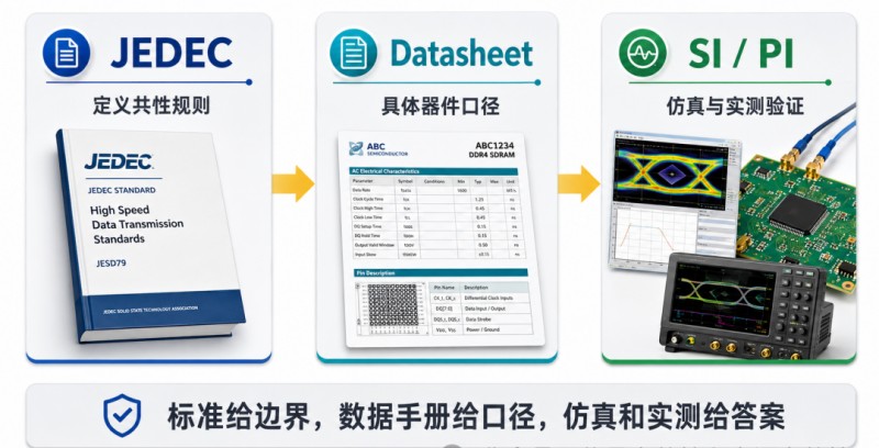
4. Combine datasheets, reference designs, and simulations. Truly mature engineering practices should integrate these three layers:
JEDEC: Review general guidelines;
Datasheets/Design Guidelines: Review specific device and platform implementation recommendations;
SI/PI Simulation + Field Testing: Verify whether your system truly falls within the safe operating range.
Ⅸ. How should you approach JEDEC if you're just starting to learn DDR?
For beginners, directly delving into the entire standard document can be quite daunting, as it's filled with terminology, state machines, timing tables, and exception conditions. A better approach is to read with specific questions in mind:
• First, understand the basic roles of DDR: what do the Controller, PHY, DRAM, and DIMM do?
• Then, look at the signals, commands, and timings defined in JEDEC;
• Next, map these rules to the actual access process: how are ACT, READ, WRITE, PRECHARGE, and REFRESH interconnected?
• Finally, return to the engineering: why do these rules affect eye diagrams, Vref, ODT, Training, and stability?
You'll find that JEDEC is more than just a "standard document"; it's like a grammar book for understanding the entire world of DDR. However, this grammar book won't tell you how to write a high-scoring essay—that part is about engineering implementation.
X. Conclusion: JEDEC Defines "Commonalities," Not "Success or Failure"
Now we can give a very clear answer to the question in the article title.
What exactly does JEDEC define?
It defines the underlying rules that the DDR industry chain must share: interfaces, electrical boundaries, command semantics, critical timing, mode registers, initialization framework, and basic compatibility behavior. Without uniformity in these elements, industry collaboration is impossible.
What does JEDEC not define?
It doesn't define how to schedule within the controller, how to implement the PHY, how to route traces on the board, how to optimize packaging, how to tune training algorithms, how to design PDN, or how to ensure mass production margins. These fall under the scope of specific product implementation and engineering optimization.
In short: JEDEC defines "how to communicate," but not "how to do things well."
Therefore, truly mature DDR engineers will not treat JEDEC as a panacea, nor will they underestimate its fundamental value. The correct approach is to establish rule boundaries using JEDEC, find specific definitions using datasheets, and solidify the system through simulation and field testing.
Finally, here's the most practical advice: Reading JEDEC isn't about "memorizing standards," but about understanding when the problem lies in comprehension of the rules and when it lies in implementation capabilities.