
Microwave Radar PCB
Let us explore in detail the key aspects of microwave radar PCB design. This type of PCB design is highly complex and serves as the core foundation for the performance and reliability of radar systems.Core Challenges: Microwave radar systems operate at GHz frequencies (commonly 24 GHz, 60 GHz, 77 GHz, and 79 GHz). At these high frequencies, signal behavior is extremely sensitive to the PCB's materials, routing, structural layout, and manufacturing processes.
Key Design Considerations:
I.Substrate Material Selection:
- Key Parameters: Dielectric constant (Dk), loss tangent (Df), consistency and stability, and coefficient of thermal expansion (CTE).
- Commonly Used Materials:
- Specialized High-Frequency Laminates: Rogers (e.g., RO3003, RO4350B, RO5880, RT/duroid 6002), Taconic (RF-35, TLY-5), Panasonic Megtron 6/7, etc. These laminates feature low loss, stable Dk, and low Df, making them suitable for millimeter-wave frequency bands.
- Standard FR-4: Generally unsuitable for core high-frequency circuitry (due to excessive loss and unstable Dk). It may be used for low-frequency control circuits, power supply sections, or as non-RF layers within a multilayer board stackup. Avoid using it within high-frequency signal paths.
II.Stackup Design:
- Multilayer Boards are the Norm:These designs require dedicated, continuous ground planes and power planes.
- RF Signal Layers:Typically placed on the top layer or the layer immediately beneath it (forming a microstrip structure), situated directly above a continuous ground plane layer. Stripline structures (where the signal traces reside in internal layers) can also be utilized, though they present greater challenges during debugging.
- Ground Planes:Crucial for performance! They must be continuous, solid, and exhibit low impedance. Avoid creating arbitrary slots or splits within the ground plane—particularly beneath high-frequency signal paths. Multiple "stitching vias" are required to ensure robust electrical connectivity between ground planes on different layers.
- Power Planes: These also require a low-impedance design and should be positioned in close proximity to their associated ICs, complemented by a network of decoupling capacitors.
III.Impedance Control:
- Precise Impedance Matching: The system's characteristic impedance is typically 50 ohms (or 100 ohms for differential pairs). The characteristic impedance is collectively determined by the width of the microstrip or stripline traces, the dielectric thickness, the copper thickness, and the dielectric constant of the substrate material. Calculation and Simulation: Professional impedance calculation tools (e.g., Polar SI9000) or electromagnetic field simulation software (e.g., HFSS, CST, ADS Momentum) must be used to perform precise calculations and optimizations.
- Manufacturing Tolerances: Maintain close communication with the PCB manufacturer to clearly define impedance control requirements (e.g., ±5% or ±10%) and ensure that their manufacturing processes can meet these specifications.
IV.Signal Integrity and Routing Rules:
- Trace Minimization: Keep trace lengths to a minimum—particularly for transmit (TX) and receive (RX) paths—to reduce path loss and phase errors.
- Curved Traces: Use large radius bends or mitered bends instead of right-angle bends to minimize reflections and discontinuities.
- Differential Pair Routing: When utilizing differential signals (e.g., reference signals in FMCW radar systems), strictly control trace length matching, spacing, and symmetry.
- Via Design:
- Minimize Quantity: Vias introduce inductance and discontinuities; therefore, use them as sparingly as possible.
- Optimize Dimensions: Smaller vias (those with smaller drill diameters) exhibit lower inductance.
- Anti-Pads: Place anti-pads (copper clearance areas) around vias on non-connecting layers to reduce parasitic capacitance.
- Back-Drilling: For deep vias, back-drill the unused portions of the barrel to remove excess metal and reduce signal reflections.
- Isolation and Crosstalk Suppression:
- Spacing: Ensure sufficient spacing between high-speed signal traces (typically 3 to 5 times the trace width, or more). TX and RX traces must be strictly isolated from one another.
- Ground Via Shielding: Place dense arrays of ground vias (forming a "via fence") parallel to both sides of critical signal traces—particularly between TX and RX paths—to create an electromagnetic shielding wall.
- Slotting/Cutouts: Create isolation slots or cutouts in the ground and power planes between TX and RX antennas or critical signal paths (exercise caution, however, to avoid compromising the integrity of the ground plane).
V.Power Integrity:
- Low-Impedance Power Distribution Network: Utilize multi-layer PCBs to provide low-inductance return paths. Employ dedicated power planes or wide power traces.
- Decoupling Strategy:
- Place large-capacitance energy storage capacitors (10µF to 100µF) at the power entry point. Medium-capacitance capacitors (0.1 µF – 1 µF) are distributed throughout the board.
- Key Principle: Place small-capacitance, high-frequency capacitors (e.g., 0.01 µF, 1000 pF, 100 pF, 10 pF) immediately adjacent to the power supply pins of RF ICs to provide a low-impedance return path for high-frequency noise. Capacitors of varying values should be connected in parallel to address noise across different frequency ranges.
- Power Domain Segmentation: Isolate sensitive power supplies—such as those for RF circuits, PLLs, and VCOs—from noisier supplies, such as those for digital logic or Power Amplifiers (PAs); utilize ferrite beads or filters for isolation where necessary.
VI.Antenna Design (for PCB-Integrated Antennas):
- Microstrip Patch Antennas: The most common type. Requires precise calculation of patch dimensions and feed-point placement. The impedance of the feedline must be strictly matched.
- Antenna Arrays: Used for beamforming applications; requires strict control over element spacing and consistency in feed-phase and amplitude.
- "Keep-out Zone" (Clearance Area): All copper foil (including ground and power planes) in the layers directly beneath the antenna region—to a depth of at least one-quarter wavelength—must be completely removed (cut out) to prevent disruption of the antenna's radiation pattern and efficiency. Sufficient clearance must also be maintained on the top layer surrounding the antenna to avoid interference from nearby metal objects.
- Simulation-Driven Design:Antenna design must rely on electromagnetic (EM) field simulation software for optimization.
VII.Thermal Management:
- Power devices (such as PAs) generate heat. The following measures should be considered:
- Increase the surface area of heat-dissipating copper pads/planes.
- Incorporate arrays of thermal vias to conduct heat from the top layer down to internal or bottom-layer copper planes.
- Create openings in the solder mask over copper pads (Solder Mask Openings) to allow for the application of solder, thereby enhancing heat dissipation.
- Utilize external heat sinks where necessary.
VIII.Test Points and Interfaces:
- Reserve dedicated RF test points (e.g., SMA connectors, microstrip probe points) to facilitate debugging and S-parameter measurements.
- Include calibration interfaces, if required.
- Select connectors that meet high-frequency performance requirements (e.g., impedance matching, low insertion loss).
IX.Manufacturing Process Requirements:
- Strict control over dimensional tolerances. Surface Finish: Electroless Nickel Immersion Gold (ENIG) is typically selected, as it provides a flat surface, excellent solderability, and suitability for gold wire bonding. Immersion Silver or Immersion Tin may also be considered. Hot Air Solder Leveling (HASL) should be avoided due to its uneven surface finish.
- High precision is required for interlayer alignment.
- Solder Mask: Select a type that has minimal impact on high-frequency characteristics.
Design Process:
- System Definition and Planning: Clearly define parameters such as frequency, bandwidth, waveform, power, sensitivity, integration level (single-chip radar IC vs. discrete components), antenna type, etc.
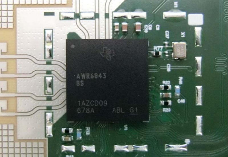
- Schematic Design: Select appropriate microwave radar chips (MMICs) and peripheral circuitry.
- Key Component Placement: Prioritize the placement of RF ICs, antennas, filters, and critical passive components.
- Stack-up Planning and Impedance Calculation: Determine the number of layers, materials, thicknesses, and target impedance values, then calculate the required trace widths.
- Detailed Layout: Adhere to high-frequency layout guidelines.
- Routing: Strictly follow rules regarding impedance control and signal integrity.
- Electromagnetic (EM) Simulation Verification: Crucial! Conduct electromagnetic field simulations (covering S-parameters, radiation patterns, crosstalk, power supply noise, etc.) both before and after the layout and routing stages.
- Design Rule Checks (DRC) and Manufacturing File Generation: Generate Gerber files, drill files, impedance specifications, Bill of Materials (BOM), etc.
- Communication with Manufacturer: Clearly articulate all special requirements and verify manufacturing capabilities.
- PCB Fabrication and Assembly: Select a reliable manufacturer with proven experience in high-frequency microwave PCBs.
- Testing and Debugging: Perform verification testing using equipment such as network analyzers, spectrum analyzers, oscilloscopes, etc.
Summary:
Designing a microwave radar PCB is a highly specialized and multidisciplinary undertaking that requires a deep understanding of high-frequency electronics, microwave theory, electromagnetic fields, transmission line theory, signal integrity, power integrity, thermal management, and advanced PCB manufacturing processes.
Simulation and verification constitute a critical phase that must never be omitted. Furthermore, close collaboration with experienced microwave PCB manufacturers is a key element for success.


