Why do SerDes receivers (RX) require CTLE, DFE, and CDR?
The signal received by the SerDes RX is no longer the crisp, square digital signal originally sent by the transmitter. It resembles a traveler who has endured a ten-plus-hour flight in economy class with two layovers and rough baggage handling: the amplitude has dropped, the edges have lost their sharpness, adjacent bits are crowding into one another, and the signal is barely sure when it should even "open its eyes."The SerDes receiver is not merely a simple comparator; it functions as a miniature "signal emergency center":
CTLE: Restoring the outline first
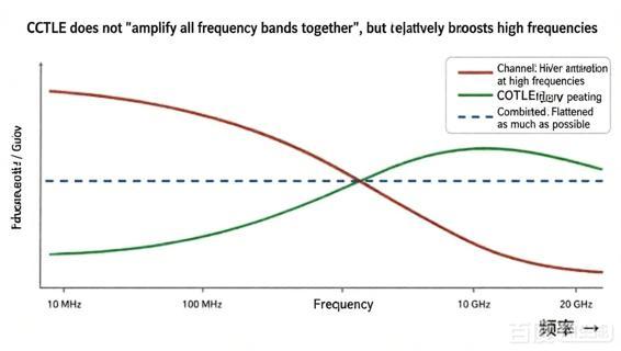
It compensates for the channel's low-pass characteristics and boosts high-frequency components, making sluggish edges distinguishable again.
DFE: Settling the "historical debt"
Based on previously determined symbols, it estimates the residual "tail" (interference) and subtracts it from the current sample value.
CDR: Deciding exactly when to "make the cut"
It recovers the clock signal from data transitions and repositions the sampling point near the center of the eye diagram.
A quick summary:
CTLE compensates for high frequencies in the "frequency domain," while DFE eliminates ISI in the "time domain."
I. What does the channel do to the signal?
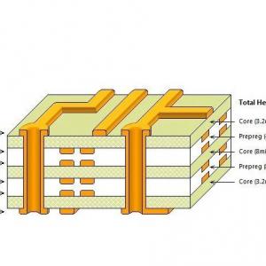
A SerDes channel typically comprises chip packaging, BGA vias, PCB traces, connectors, backplanes, copper cables, and even electrical interfaces before and after optical-electrical conversion. Each structural element contributes to loss, reflection, crosstalk, noise, and unequal time delays.1. High-frequency loss: Edges are the first to be degraded
PCB dielectric loss and conductor loss generally increase with frequency. Digital edges are steep because they contain rich high-frequency harmonics; when high-frequency components are attenuated first, the edges become slower (less sharp).2. Pulse spreading: The preceding bit interferes with the following bit
In a real-world channel, the pulse response exhibits "tails" that trail both forward and backward. The sampled value of the current symbol is no longer determined solely by the current bit; it is also influenced by preceding (and sometimes subsequent) symbols. This phenomenon is known as Inter-Symbol Interference (ISI).
r[n] = a0x[n] + a1x[n−1] + … + noise
Don't be intimidated by the equation. In plain language: the voltage level you see right now doesn't just belong to the "present"; it also carries lingering traces of the "past."3. Jitter: The sampling instant begins to waver
Amplitude distortion is only half the story. Factors such as crosstalk, power supply noise, PLL phase noise, duty cycle distortion, and reflections cause signal edges to jitter back and forth along the time axis. As the eye diagram narrows horizontally, the time window available for safe sampling at the receiver shrinks.
II. CTLE: Boosting the edges first
CTLE stands for Continuous-Time Linear Equalizer. It is typically located in the receiver's (RX) analog front-end and operates before the signal undergoes sampling and decision-making.The core concept of CTLE is this: since the transmission channel acts like a low-pass filter—attenuating high frequencies more severely than low frequencies—the receiver applies a response with high-frequency peaking to flatten the overall frequency response.
CTLE is a linear equalizer. While it boosts high-frequency signals, it simultaneously amplifies thermal noise, crosstalk, and some random noise within that same frequency band. It is akin to sharpening a blurry photo: the outlines become clearer, but the background grain may also become unpleasantly pronounced.
A higher CTLE setting does not necessarily mean a better link.
Excessive peaking can lead to noise amplification, overshoot, ringing, saturation in downstream stages, and an increased bit error rate (BER). In engineering, the goal is not to achieve the "most aggressive curve," but rather to minimize the final BER and maximize the eye diagram margin.
III. DFE: Subtracting the Residual Tail
Even after the CTLE has shaped the overall frequency response into a more desirable form, residual post-cursor ISI (Inter-Symbol Interference), reflections, and crosstalk within the channel may still be significant. This is where the DFE comes into play.
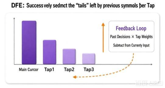
DFE stands for Decision Feedback Equalizer. Its core logic is: "Since I already know the decisions made for previous symbols, I can estimate the 'tail'—or residual interference—they leave at the current sampling point and subtract it beforehand."
z[n] = r[n] − h1â[n−1] − … − hKâ[n−K]
Here, â[n−1] represents the previously decided symbol, while h1, h2, etc., are the weights for the various DFE taps. If the first post-cursor is the most severe, the weight for Tap 1 is typically the largest; conversely, if a connector reflection occurs after 3 UIs (Unit Intervals), Tap 3 might play a particularly critical role.
The DFE's greatest advantage: it does not linearly amplify input noise along with the signal.
Instead of simply applying high-frequency gain to the analog input, the DFE uses discrete decision results to cancel out deterministic post-cursor interference. Consequently, it is highly effective against severe post-cursor ISI and avoids the issue seen with CTLEs, where in-band noise at the input is amplified across the board.
This is why CTLEs and DFEs are often used in tandem for long backplanes, multi-connector setups, or high-loss links: the CTLE brings the signal back into the decodable range, while the DFE precisely cleans up residual trailing effects. One handles "broad-spectrum restoration," while the other performs "targeted cleanup."
The DFE's downside: a single misjudgment can trigger a chain reaction.
The DFE relies on the assumption that previous decisions were correct. If a symbol is misidentified, the erroneous result enters the feedback path and affects subsequent Unit Intervals (UIs)—a phenomenon known as error propagation. It is akin to entering an invoice incorrectly at the start; if subsequent reports reference that error, the finance department will eventually stare at you in silence for three full minutes.
IV. CDR: Sampling after waveform conditioning
Clock information is embedded within data transitions; the receiver (RX) must extract the sampling timing directly from the data stream. This process is known as CDR—Clock and Data Recovery.Even if the eye diagram is vertically open, frequent errors will still occur if the sampling point falls too close to the signal edges. The CDR's task is not merely to calculate the frequency, but to continuously track phase variations in the input data and align the sampling instant as close to the center of the eye diagram as possible.
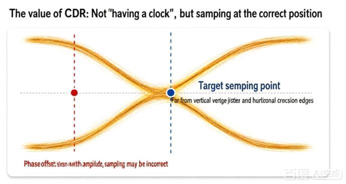
What generally happens inside a CDR?
A typical CDR comprises a phase detector, a loop filter, a VCO/DCO, and a frequency-divider or multi-phase clock structure. The phase detector monitors whether data transitions occur "early" or "late" relative to the local clock; the loop then adjusts the local clock accordingly until the frequency and phase fall within the usable range.
V. Why are all three indispensable? Because they address different problems.
A simple way to remember:CTLE is responsible for "sharpening the photo," DFE for "eliminating ghosting," and CDR for "keeping your hand steady when snapping the picture." Only when all three tasks are performed well does the RX stand a chance of correctly recovering the 0s and 1s.
VI. Not just lining up for work, but mutually influencing each other
Channel → CTLE → DFE → CDRThe CTLE sits in the analog front-end, while the sampler, DFE, and CDR form a tightly coupled system. The CDR provides the sampling phase, and the DFE uses sampling decisions for feedback; in turn, the clearer signal transitions resulting from equalization help the phase detector operate stably. Many receivers perform joint adaptive tuning of gain, CTLE, DFE, and phase during the lock-in process.
This creates a classic "chicken-and-egg" problem:
The CDR needs relatively clear transitions to lock;
The DFE needs relatively reliable decisions and clock timing to converge correctly;
The CTLE needs to select the right setting, yet often relies on eye height, eye width, or bit error rate (BER) metrics to evaluate performance.
VII. Why is PAM4 so much harder to handle?
NRZ has only one decision threshold and one eye; PAM4 has four voltage levels, three decision thresholds, and three eyes. When the same peak-to-peak swing is divided into three segments, the vertical margin of any single eye is inherently smaller.This compounds the challenges for the CTLE, DFE, and CDR:
- CTLE: If high-frequency peaking is slightly excessive, noise can cross the threshold of an adjacent level; not all three eyes necessarily benefit simultaneously.
- DFE: Feedback symbols are no longer limited to ±1; tap calculations and multi-level decision-making are more complex, and error propagation is trickier to manage.
- CDR: Zero-crossing positions, nonlinearity, and noise sensitivity vary depending on the amplitude of the transition, requiring greater caution in phase detection.
VIII. Viewing the Entire RX as a Rescue Team
Revisiting the SerDes receiver with this perspective, the CTLE, DFE, and CDR no longer seem complex merely for the sake of complexity. Each addresses a fundamental impairment affecting high-speed channels:Distorted Frequency Response
High-frequency loss slows down signal edges; the CTLE restores the balance between high and low frequencies.
Intersymbol Interference (ISI)
Pulse tails and reflections cause post-cursor ISI; the DFE subtracts this interference based on historical decisions.
Loss of Sampling Timing Reference
The clock is embedded in the data and subject to jitter; the CDR recovers frequency and phase to drive the sampling process.
A truly excellent RX isn't defined by extreme parameters in any single module, but by the perfect coordination of all three: the CTLE avoids excessive noise amplification, the DFE prevents error propagation (avoiding a "soap opera" of cascading errors), and the CDR tracks low-frequency drift without fruitlessly chasing high-frequency jitter.
CTLE shapes the signal, DFE removes tails, and CDR manages timing—together, they transform a bitstream mangled by the channel back into reliable data that the chip can trust.