RF PCB Material Selection: FR-4, Rogers, or PTFE—Which One Should You Use?
The PCB substrate serves as the "foundation" of an RF circuit. If the wrong material is chosen, it is difficult to replicate simulation results in actual measurements. Today, we will explore the parameters, pricing, and application scenarios of three types of substrate materials.For consumer electronics operating below 1 GHz, FR-4 is sufficient. For microwave circuits in the 1–10 GHz range, RO4350B offers the best cost-performance ratio. At millimeter-wave frequencies (above 10 GHz), PTFE (such as the 5880 series) is required. In the intermediate range, mixed-stackup solutions can be used to save costs with negligible impact on performance.
I. Dk, Df, and TCDk
Selecting a substrate material essentially involves making trade-offs:- Dk (Relative Permittivity): Determines the signal propagation speed within the dielectric, which in turn dictates trace width and dimensions. A higher Dk results in narrower traces for a given impedance, making the design more sensitive to manufacturing tolerances.
- Df (Dissipation Factor/Loss Tangent): Determines dielectric loss. A higher Df means more high-frequency energy is "lost" (dissipated as heat) within the dielectric.
- TCDk (Temperature Coefficient of Dk): Determines how much the Dk drifts with temperature changes. A higher TCDk causes the center frequency of your filter to shift further as the temperature changes.
α_d ∝ f × tanδ × √ε
Note this relationship: insertion loss is directly proportional to frequency. At 1 GHz, the loss of FR-4 is negligible; at 10 GHz, with the same dissipation factor (Df), the loss is ten times greater. This explains why performance at low frequencies is not an issue, whereas at high frequencies, it becomes problematic.
II. FR-4: Sufficient for these situations
Parameters (Typical Values)
FR-4
Dk @1GHz
4.2 ~ 4.7
Df @1GHz
0.015 ~ 0.025
Dk @10GHz
~4.0 ~ 4.2 (Significant decrease)
Dk Batch Consistency
Poor (±0.2~0.3)
Moisture Absorption Rate
~0.1%
Relative Cost
Baseline 1x
When is it sufficient?
- Frequencies below 1 GHz with short RF traces (much less than 1/4 wavelength).
- 2.4/5 GHz WiFi and Bluetooth applications where RF traces are only a few millimeters long and insertion loss is not a critical concern.
- Consumer electronics that are cost-sensitive and produced in high volumes.
Practical tip: For a 2.4 GHz Bluetooth antenna, the feed line is usually just a few millimeters long; FR-4 handles this perfectly well, so there is no need to use Rogers materials. However, if you are designing output matching for a WiFi power amplifier (PA) or a 5.8 GHz power divider, FR-4 falls short.
The core issue with FR-4 is drift. It is common for the dielectric constant (Dk) to drift by ±0.2–0.3 between batches, and to drop by another 0.3–0.5 as the frequency rises from 1 GHz to 10 GHz. What are the consequences? With the same matching network design, switching to a different batch of board material can cause the resonant frequency to shift by 2–3%, and filter center frequencies to drift with temperature changes. While this may not matter in low-frequency bands, it is disastrous in the microwave range.
III. Rogers: The All-Rounder for Microwave Applications
The Rogers materials discussed here primarily refer to the RO4350B / RO4003C family. These are hydrocarbon resin boards filled with ceramic and reinforced with glass fiber. They are—without a doubt—the most widely used board materials in the RF industry.
Parameter
RO4350B
Dk @10GHz
3.48 ± 0.05
Df @10GHz
0.0037
TCDk
Approx. +50 ppm/℃ (Official range -50 ~ +115℃)
Moisture Absorption
0.06%
Relative Cost
5~10x of FR-4
Why is it an "all-rounder"? Here are three reasons:
- Stable Dk: Batch-to-batch consistency of ±0.05 ensures reproducible filter and matching network designs—something FR-4 cannot achieve.
- Low loss: The Df is only about one-fifth that of FR-4; at 10 GHz, microstrip insertion loss is approximately 0.18 dB/inch, whereas FR-4 is in the range of 1 dB/inch.
- Process compatibility: It can be processed using standard FR-4 workflows—fully compatible with drilling, milling, lamination, and copper plating—giving it a decisive advantage over PTFE.
By the way, domestic hydrocarbon-based laminates have advanced rapidly in recent years (companies like Shengyi, Huazheng, and Jinan Guoji all offer products comparable to RO4350B); performance is nearly identical, yet the price is more than 30% lower. When selecting materials for the microwave band, there is really no longer a strict need to insist on Rogers.
IV. PTFE: The Ultimate Choice for Millimeter-Wave Applications
Representative examples: RT/duroid 5880 (Dk 2.20) and 5870 (Dk 2.33).
Parameter
RT/duroid 5880
Dk @10GHz
2.20 ± 0.02
Df @10GHz
0.0009
TCDk
-125 ppm/℃
Moisture Absorption
0.02%
Relative Cost
12~20x of FR-4
Advantages of 5880:
- Df of 0.0009—more than an order of magnitude lower than FR-4.
- Low and uniform Dk (±0.02); the longer wavelength within the dielectric and wider trace widths dilute the impact of manufacturing tolerances.
- Insertion loss for a 10GHz microstrip line is approximately 0.10 dB/inch; it is the gold standard for the millimeter-wave band.
- The material is soft and prone to deformation; drilling burrs and edge delamination during milling are common issues.
- Plasma or sodium-naphthalene treatment is mandatory prior to copper deposition; otherwise, via metallization reliability is compromised.
- It cannot be directly co-laminated with FR-4 due to incompatibilities in CTE and processing methods; specialized workflows are required.
Applications: Frequencies above 10GHz—such as 77GHz millimeter-wave radar, low-noise amplifiers (LNAs), and satellite communication front-ends.
V. Distribution Disparities
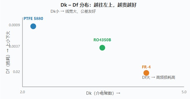
▲ Figure 1: Dk-Df positioning of three types of laminates. 5880 (low loss, low Dk) is at the top left,
RO4350B (balanced) is in the middle, and FR-4 (high loss, high Dk) is at the bottom right.
RO4350B occupies the central position, which is the reason for its "versatility."
Pairing this with insertion loss data provides a more intuitive perspective (50Ω microstrip line, 10 GHz):
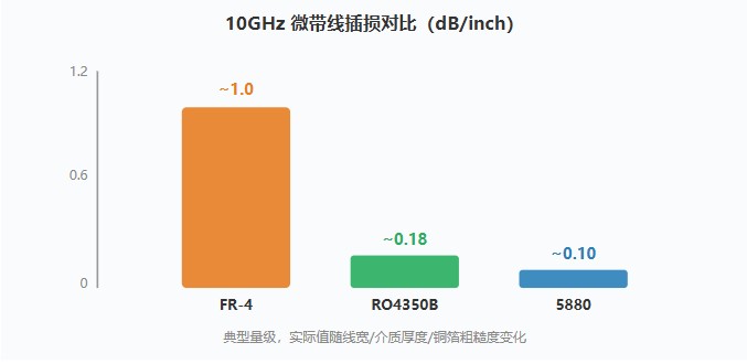
▲ Figure 2: For the same 50Ω microstrip line, the insertion loss of FR-4 is more than five times that of RO4350B and ten times that of 5880.
For a 10 GHz microstrip line with a length of 5 cm (approx. 2 inches), signal loss is as follows: FR-4 incurs about 2 dB of loss (a 37% reduction in power), while RO4350B and 5880 incur approximately 0.36 dB and 0.2 dB, respectively. This is how the choice of board material consumes the front-end noise budget and link gain margin.
VI. Mixed Stack-up: Cost-Efficiency is Key
Using Rogers materials for high-frequency layers and FR-4 for low-frequency and power layers—bonded together into a single board—is the most common cost-saving strategy for RF PCBs.A classic mixed-stack-up scheme for a 6-layer board:
| Layer | Material | Thickness | Application |
| L1 | RO4350B | 0.254mm (10mil) | RF Trace Layer |
| L2 | FR-4 | — | Solid Ground Plane |
| L3~L5 | FR-4 | — | Power / Low-Speed Signal |
| L6 | FR-4 | — | Bottom Layer |
Key considerations for mixed lamination:
- Drilling: There is a significant difference in hardness between Rogers and FR-4 layers; drilling them together results in poor hole-wall quality, so separate drilling passes are recommended.
- Lamination: RO4350B can withstand standard FR-4 processing temperatures—a prerequisite for mixed lamination (unlike PTFE materials).
- Reliability: Mixed-laminate boards must pass thermal cycling tests (e.g., JESD22-A104) to ensure no delamination occurs.
- Warpage: Use the same dielectric thickness on both sides whenever possible to minimize board warpage.
VII. Decision Quick-Reference Table
| Application Scenario | Recommended Laminate | One-Sentence Reason |
| Below 1GHz, short traces | FR-4 | Low cost and fully sufficient for use |
| 2.4/5GHz, short feed lines | FR-4 | Signal loss is acceptable |
| 2.4/5GHz Power Amplifier / Front-End | RO4350B | Highly sensitive to insertion loss, high-frequency material is mandatory |
| 1~10GHz Microwave Circuits | RO4350B / RO4003C | Stable Dk value + compatible with standard PCB processes |
| Millimeter wave above 10GHz | 5880 / 5870 / LCP | Ultra-low transmission loss |
| High-Speed Digital (SerDes/DDR5) | Low-loss FR-4 (Megtron 6/7 etc.) | Balances cost and signal loss performance |
| Phased Array / Radar T/R Modules | Rogers Hybrid Lamination | Achieves ideal balance between performance and cost |
Let’s address high-speed digital applications separately: for technologies like SerDes exceeding 10Gbps and DDR5, the industry standard has shifted to low-loss FR-4 materials—such as Panasonic’s Megtron 6/7 and comparable series from domestic manufacturers like Shengyi and ITEQ (with a Df of approximately 0.002–0.004)—rather than Rogers materials. These materials feature a Dk of 3.3–3.4, are fully compatible with standard FR-4 manufacturing processes, and are specifically optimized for high-speed digital signals. Furthermore, the recent surge in demand for AI servers and 800G switches has rapidly popularized this category; materials at the Megtron 8 level (with Df further reduced to below 0.002) are already shipping in high volumes. When selecting materials, be sure to ask the PCB manufacturer if they have "M8-grade production capacity." Do not simply apply RF material selection logic to high-speed digital designs.
VIII. Five Common Issues
- Ignoring copper foil roughness. High-frequency currents exhibit the skin effect, flowing entirely along the copper foil's surface. Standard HTE (High-Temperature Elongation) copper foil has a rough surface; in the millimeter-wave range, surface loss can account for over 30% of total insertion loss. For millimeter-wave applications, you must specify VLP (Very Low Profile) or HVLP (Hyper Very Low Profile) copper foil; do not let the manufacturer default to standard copper foil.
- Moisture absorption in the substrate. When FR-4 absorbs moisture, both Dk and Df deteriorate—an effect that is particularly pronounced in the microwave range. In humid regions (such as during the "Return of the South Wind" season), if bare boards are taken directly from inventory to the assembly line, test results may differ significantly from those obtained under dry conditions. Microwave boards undergo a baking process before leaving the factory; do not skip this step.
- Ignoring TCDk (Temperature Coefficient of Dielectric Constant). Consider a 5GHz filter using RO4350B (TCDk ≈ +50 ppm/°C): if the temperature rises from 25°C to 85°C (ΔT = 60°C), the frequency drift is 5GHz × 50 × 10⁻⁶ × 60 = 15MHz. If FR-4 is used instead (where TCDk is typically in the range of 200 ppm/°C and often not guaranteed by manufacturers), the drift increases by a factor of 3 to 5. For designs requiring temperature stability, TCDk must be included in the material selection criteria.
- Treating PTFE like FR-4. Simply handing 5880 material to a standard PCB manufacturer to process using FR-4 workflows leads to disastrous results—such as delamination during drilling and fractured barrel plating—resulting in abysmal yields. PTFE requires a manufacturer experienced in RF board fabrication, with advance confirmation of critical processes like plasma treatment, drilling parameters, and lamination temperatures.
- Ignoring the fiberglass weave effect. This is the most frequently overlooked PCB material issue in high-frequency/high-speed designs over the past decade. In FR-4, the E-glass fabric has a dielectric constant (Dk) of approximately 6.1, while the surrounding resin is around 3.3; because they are woven together, the Dk fluctuates periodically at a scale of 0.2–0.3 mm.
As high-frequency signals propagate along traces, they alternately pass through "glass fiber bundles" and "resin-rich areas," causing localized impedance fluctuations and inconsistent phase delays. Many issues—such as inexplicable anomalies in microstrip S-parameters and degraded eye diagrams for high-speed signals like PCIe Gen5 or DDR5—are linked to this phenomenon.
Solution: Specify low-Dk glass (e.g., NE-glass with Dk ≈ 4.5, or L-glass, which is even lower) or flat-weave glass fabric (spread-glass fabric). This is also a key reason why Rogers materials—which commonly utilize flat-weave glass—exhibit more stable high-frequency performance.