KEY TECHNOLOGY(HK)CO. ,LIMITED
  • Home
  • Products
    • PCBA
    • Rigid PCB
    • HDI PCB
    • Rigid Flex PCB
    • Flex PCB
    • High Frequency PCB
      • Rogers PCB
      • Isola PCB
      • Arlon PCB
      • Nelco PCB
      • Taconic PCB
      • Teflon PCB
      • Neltec PCB
    • Metal Core PCB
      • Aluminium PCB
      • Copper PCB
    • Ceramic PCB
    • Laser Stencil
    • Reverse engineering
    • Purchasing components
  • Capability
    • PCBA capability
    • Rigid PCB capability
    • HDI PCB Capability
    • Rigid Flex PCB Capability
    • Flex PCB Capability
    • High Frequency PCB Capability
    • Metal Core PCB Capability
    • Ceramic PCB Capability
  • Equipment
    • PCB Equipment
    • PCBA Equipment
  • About us
  • Blogs
  • Feedback
  • Contact us

Blogs

  1. Home
  2. Blogs
  3. Improper PCB layout...

Improper PCB layout

Improper PCB layout


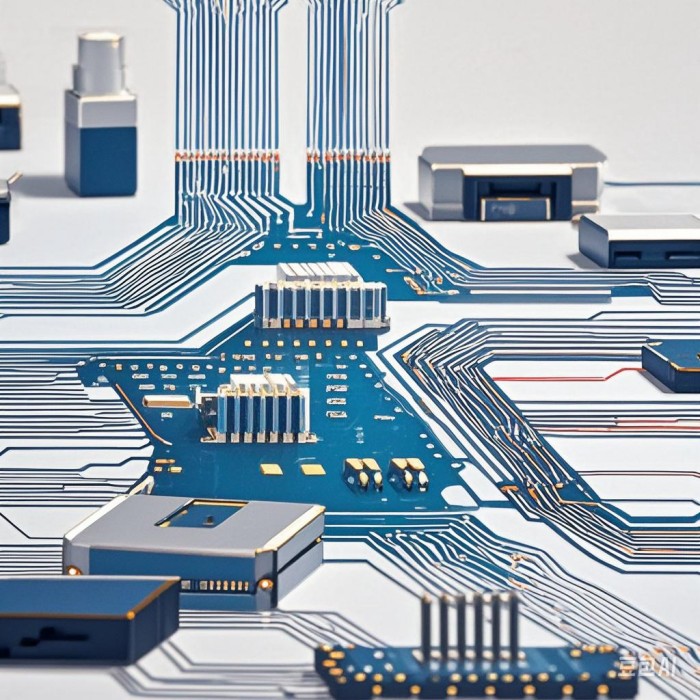
The situations of unreasonable PCB routing and corresponding examples are as follows:

Unreasonable PCB Conductor Width

- Too Narrow Conductor Width of PCB: For example, if the width of a high-frequency signal transmission line of PCB is designed to be too narrow, the PCB Conductor resistance will increase, causing the signal to attenuate more severely during transmission and resulting in poor signal quality at the receiving end. Meanwhile, when a large current passes through a PCB Conductor that is too narrow, it is prone to burning out due to PCB overheating, thus affecting the normal operation of the PCB circuit.
- Too Wide Conductor Width of PCB: It will occupy too much routing space, making it difficult to route other Conductors, increasing the routing difficulty. It may also enhance the coupling between signals and cause crosstalk.

Unreasonable PCB Routing Spacing

- Too Small Spacing of PCB: If the PCB spacing between adjacent routed lines is too small, insulation breakdown is likely to occur in a humid environment or under high voltage, leading to PCB short-circuit faults. For instance, if the PCB spacing between the power layer and the ground layer is too small, an inter-layer short circuit may occur.
- Too Large Spacing of PCB: It will increase the size of the PCB, raising the cost, and also increase the PCB signal transmission delay, affecting the high-speed performance of the system.

Unreasonable PCB Routing Direction

- Right-Angle Routing: It will cause signal reflection at the corners, damaging the PCB signal integrity. For example, when PCB high-speed digital signals are routed at right angles, serious reflection will occur, resulting in overshoot, undershoot, and ringing phenomena of the signal, increasing the bit error rate.
- Excessively Long Parallel Routing: Excessively long parallel routing on adjacent layers or the PCB same layer will enhance the electromagnetic coupling between signals and cause crosstalk. For example, if the PCB clock signal and the PCB data signal are routed in parallel for too long, the data signal may be interfered by the clock signal, leading to data transmission errors.

Failure to Route According to Functional Areas

- Mixing Analog and Digital Signals in PCB Routing: When analog signals and digital signals are routed in the same area, the PCB high-frequency noise in the digital signals will interfere with the analog signals, reducing the accuracy of the analog signals. For example, if the analog input signal of an audio amplifier is routed together with the digital control signal, there will be noise in the audio signal.
- Mixing Power and Signal Routing : If the PCB power routing and the PCB signal routing are not separated, the noise on the power conductor will couple to the signal conductor, affecting the PCB signal quality. For example, if the power routing of a CPU is close to the address signal routing, the CPU may work abnormally.

Related News

FR-4 PCB Manufacturing process-Final inspection

FR-4 PCB Manufacturing process-Final inspection

Analysis and discussion on the cause of slight stains on the PCBA coating?

Analysis and discussion on the cause of slight stains on the

Discussion on the solution to PCB warping

Discussion on the solution to PCB warping

Why can't I hit the via hole on the pad? I just want to punch, what should I do?

Why can't I hit the via hole on the pad? I just want to punc

PCB design: PCB board design process

PCB design: PCB board design process

What is the meaning of the

What is the meaning of the "false eight" in the PCB stack?

Product Categories

  • PCBA
  • Rigid PCB
  • HDI PCB
  • Rigid Flex PCB
  • Flex PCB
  • High Frequency PCB
    • Rogers PCB
    • Isola PCB
    • Arlon PCB
    • Nelco PCB
    • Taconic PCB
    • Teflon PCB
    • Neltec PCB
  • Metal Core PCB
    • Aluminium PCB
    • Copper PCB
  • Ceramic PCB
  • Laser Stencil
  • Reverse engineering
  • Purchasing components

Links

Google.comBaidu.com

内页左侧广告1

Feedback

Contact Us

sales@key-pcba.com

234123644@qq.com

Commercial and Cultural Building, Community 11 of Tangwei,Fuhai Street, Bao'An District Shenzhen 518103 GuangDong China.

WECHAT

Copyright © 2016 KEY TECHNOLOGY(HK)CO. ,LIMITED All Rights Reserved.

  • Skype.
  • E-mail
  • Whatsapp
  • Inquiry