Description
A radar PCB is a printed circuit board specifically designed for radar systems. It integrates high-frequency circuitry and antenna structures to transmit, receive, and process electromagnetic waves, and is widely used in automotive, IoT, and aerospace industries.
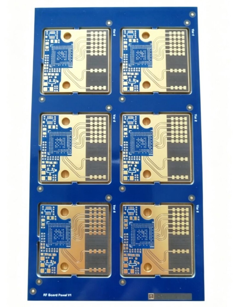
These PCBs typically use high-frequency materials (such as Rogers RO4350B) to reduce signal loss and utilize microstrip antennas or patch arrays for electromagnetic wave transmission and reception.
Their core operating principle is largely based on frequency-modulated continuous wave (FMCW), enabling precise measurement of target distance, speed, and angle.
In the automotive field, 77GHz millimeter-wave radar PCBs are used in advanced driver assistance systems (ADAS) such as adaptive cruise control and automatic emergency braking, requiring a wide operating temperature range of -40℃ to 150℃ and high reliability.
In smart homes, 5.8GHz or 24GHz radar PCBs can be used for human presence detection and gesture recognition, featuring low power consumption and high sensitivity.
The main challenges in manufacturing millimeter-wave radar PCBs lie in three areas: high-frequency signal processing, material processing precision, and long-term reliability. Even slight negligence can lead to signal distortion, performance degradation, or even system failure.
I. Core Manufacturing Challenges
1. High-Frequency Material Processing Difficulties: Millimeter-wave radar (e.g., 77GHz) requires PCBs made of low-loss materials (such as PTFE and Rogers RO4350B). However, these materials are soft, have high coefficients of thermal expansion, and are prone to deformation during lamination and lateral etching during etching, resulting in inaccurate linewidth control.
While hybrid lamination structures (high-frequency layer + FR-4) can reduce costs, the significant differences in thermal stress between different materials can easily lead to warping and delamination during lamination.
2. Extremely High Impedance Control Precision Requirements: Millimeter-wave signals are extremely sensitive to impedance matching. The 50Ω impedance tolerance must be controlled within ±3%. A deviation in linewidth/dielectric thickness exceeding ±0.005mm will cause signal reflection and abnormal VSWR.
In transmission line designs such as microstrip lines and coplanar waveguides, via stubs can cause resonance, which must be eliminated through back-drilling or blind via processes.
3. Significant Challenges in Microstructure Manufacturing: Antenna array elements are micrometer-sized, requiring etching precision of ±0.02mm; otherwise, beam pattern and sidelobe suppression will be affected.
Grounding via array spacing must be less than λ/10 (approximately 0.5mm at 77GHz), necessitating laser drilling technology with extremely high hole alignment accuracy.
4. Surface Treatment and Soldering Risks: While immersion silver plating is low-cost and offers good conductivity, silver migration can easily occur, forming conductive paths and causing short circuits in high-temperature and high-humidity environments.
Although ENIG (nickel-palladium-gold alloy) is commonly used, the "black disk" problem can lead to poor solder joints, affecting long-term reliability.
II. Key Considerations
- Material Selection: Prioritize high-frequency substrates with a Df < 0.004, such as Rogers series or PTFE composite materials. If cost is a constraint, a hybrid design of "high-frequency surface layer + FR-4 bottom layer" can be used.
- Layer Stack Design: Employ a symmetrical structure to reduce warpage. The core signal layer should be adjacent to a complete ground plane to avoid cross-segmentation.
- Manufacturing Process: Use an LDI exposure machine (accuracy ±0.01mm) and high-frequency etching lines to ensure linewidth consistency. Employ ultrasonic-assisted silver plating to improve the uniformity of micro-pad plating. Perform 100% AOI + X-ray inspection on critical signal paths to ensure defect-free operation.
- Environmental Adaptability: Finished products must pass a temperature cycling test from -40℃ to 150℃ to ensure no delamination or cracking under harsh automotive environments.
- Post-validation: The S-parameters (S11, S21) must be tested using a vector network analyzer (VNA) to confirm that the return loss is ≥18dB and the insertion loss is ≤0.2dB/in@60GHz.


